Robotic Nanomanipulation with an SPM in a Networked Computing Environment
C. Baur, B. C. Gazen, B. Koel, T. R. Ramachandran, A. A. G. Requicha, and L. Zini
Laboratory for Molecular Robotics, University of Southern California, Los Angeles, CA 90089-0781, U.S.A.
This paper describes the initial phase of the development of a high-level programming system for robotic manipulation with a Scanning Probe Microscope (SPM). We have developed an SPM server, which runs in the Windows environment of the PC that controls the microscope. Client programs running on Unix workstations or other computers connected to the Internet can send remote commands to the SPM through the server. The clients can be sophisticated Artificial Intelligence programs that reason about robotic tasks and sensory data acquired by the SPM. We have also developed a first set of intermediate-level commands for sensing and manipulation. The system is being tested by pushing colloidal gold nanoparticles with dimensions in the order of 15-30 nm on a mica substrate in non-contact AFM mode. The test programs image the sample, search for nanoparticles in the presence of thermal drift, turn feedback on and off for pushing, and so on. We are moving the particles reliably.
I. INTRODUCTION
The Laboratory for Molecular Robotics at the University of Southern California is an interdisciplinary research laboratory whose ultimate goals are the development of a high-level programming system for robotic manipulation with an SPM (Scanning Probe Microscope), and its use in challenging applications such as building nanomachines or DNA manipulation. Ultimately we expect to be able to process very high level commands such as “assemble object X with object Y”, where X and Y might be, for example, molecules or nanoparticles. Robotic systems at the nanoscale must, like their macroscopic brethren, sense, “think” and act. The SPM is both a sensor and an actuator. But we must provide it with the intelligence necessary for reliably executing complex commands. This requires sophisticated Artificial Intelligence (AI) programming and software tools that typically run on Unix workstations.
Previous research shows that it is possible to position with an SPM atoms, molecules, nanoparticles, and liquid droplets [1, 2, 3, 4]. The reported approaches exhibit one or more of the following characteristics:
- Careful selection of substrates and objects to be moved.
- Trial-and-error determination of SPM parameters for imaging and manipulation.
- Operation in UHV (ultra high vacuum) and/or low temperature.
- Time-consuming user-interactive manipulation.
- Custom software developed, typically for an IBM-compatible PC.
In the macroworld, robots typically are programmed by technicians or bachelor-level engineers, and execute reliably and routinely thousands of tasks per day in industrial environments. In contrast, nanomanipulation today is more of an experimental tour-de-force, accomplished in careful experiments run by Ph.D.-level researchers in a few laboratories, than a useful technique that can be used routinely for practical purposes. The work in our laboratory seeks to make nanomanipulation tasks much easier to program and execute reliably, so as to transform nanomanipulation into a mainstream technique, much like its macroscopic counterpart.
Commercially-available software for SPMs typically runs on stand-alone PCs. The growth of the Internet and the difficulty of co-locating personnel in interdisciplinary research endeavors (e.g., our own lab is spread across several buildings) both point to the need for distributed software systems. PCs are not the platforms of choice for the development of intelligent systems in a distributed environment, and research institutes tend to have a heterogeneous computing environment, with most of the sophisticated programming being done in Unix workstations. For these reasons, software that makes the SPM behave as a network “peripheral” is very desirable. The SPM becomes thus available to programs running on any computer in the Internet. This also has the advantage of making net resources such as printers and mass storage readily available to SPM users.
Commercial SPM hardware and software are primarily directed at imaging. However, manipulation and imaging have different requirements. One can envisage at least two strategies for developing SPM nanomanipulation facilities. The first consists of designing and building from scratch a custom instrument, together with its low-level and high-level control software for manipulation tasks. This may lead to optimal results but requires substantial resources in terms of time, money and personnel. An attractive alternative, discussed in this paper, starts from commercially-available hardware and low-level control software, and builds higher-level layers of software upon them.
The remainder of this paper is organized as follows. First we describe an SPM server that provides communication facilities for using the SPM transparently in a network. Next we discuss some of the intermediate-level manipulation commands we have developed. Then we present experiments in nanomanipulation that use our software, and conclude with a brief assessment of our current manipulation capabilities and open issues.
II. SPM SERVER
We are using an AutoProbe CP instrument, a commercially-available SPM developed by PSI (Park Scientific Instruments). The SPM software is a 16-bit application that runs in IBM-compatible PCs under Windows 3.1 or Windows 95. It includes a modern graphic user interface, through which a user issues commands. These are translated and sent to a Digital Signal Processor (DSP) that controls the instrument. Importantly, PSI also provides an Application Programming Interface (API) to its software. This API is meant to be used by experienced programmers. We think that working through a commercial API has significant advantages. It lets a programmer issue low-level commands without having to get involved in the intricacies of the DSP and real-time control, which are best left to the manufacturer. It also greatly facilitates software maintenance, since it relies on the manufacturer to ensure that new developments in hardware and low-level software are smoothly incorporated into the system through the API.
In Unix systems a process running in one machine can invoke procedures that reside in a different machine through a Remote Procedure Call (RPC). Unfortunately RPCs are not supported in the Windows 3.1 or Windows 95 environments. To achieve similar functionality one can use an SPM server that listens to requests for SPM operations issued by computers in the network, and takes the appropriate actions. Typical commercial computer communication packages, for example Sun Microsystems’ PC-NFS, are aimed at building PC clients, and do not directly support PC servers. Because powerful tools such as socket libraries are available, building a server is not a large task for a computer scientist versed in distributed systems. (A socket is a programming abstraction that corresponds to a communication port through which messages can be sent or received.) Furthermore, commercial systems normally do not provide access to source code, which we believe is important for a research group that is exploring new approaches and techniques that may require intimate knowledge of the software. For these reasons, we decided to develop an SPM server, as explained below.
The PC that controls the SPM is connected to our Ethernet Local Area Network through an Ethernet card. The SPM server is a Windows application that uses a standard interprocess communication library called Winsock. The server opens a socket into the network and listens to requests from client processes running on other machines. These clients issue requests by calling a Unix-standard socket library. Both Winsock and the Unix socket library use the standard TCP/IP protocols, but they isolate the programmer from the low-level details of how communications between computers are achieved. Socket programming is a relatively straightforward exercise. The clients’ requests are decoded, mapped into API routines, and appropriate API calls are issued. (Examples of API calls are given in the next section.) The results of API routine execution are received by the server, encoded for transmission, and sent back to the requesting process. We encode the messages in XDR (External Data Representation) format, which is a de facto standard introduced by Sun Microsystems.
We wrote a library of C procedures that mirror those provided in the SPM’s API, and run on Unix workstations. These procedures exchange information with the PC through the network, by using sockets. A client program running in a Unix workstation invokes procedures in this library, and is unaware of the network communications involved. In essence, the messages sent by a client correspond to API calls, and the messages it receives correspond to the results returned by the API routines called. More sophisticated capabilities are being built on the client side, on top of the low-level API.
III. MANIPULATION COMMANDS
The graphic user interface supplied by PSI is designed for imaging and is not suitable for manipulation. But the API has powerful routines that can be used to build manipulation commands. An important low-level API procedure serves to apply ramp (i.e., linearly increasing or decreasing) signals to SPM input ports. A ramp is specified by a list of triplets (InitialValue, Slope, Duration). For example, applying two ramps with the same slope and duration to the xand y inputs of the piezoelectric scanner causes a linear motion at 45 degrees to the x axis, with a speed determined by the slope of the ramps, and starting at the specified initial point. As a second example, a step change in a SPM parameter value can be accomplished by applying two successive “ramps” of zero (horizontal) slope, starting at appropriate initial values.
By using these ramps it is easy to construct a fundamental command to move the SPM tip from (x1, y1) to (x2, y2) at speed s. In turn, this linear motion capability can be used to traverse more complex trajectories. For example, a circular trajectory can be followed by decomposing it into linear segments. More interestingly, imaging scans of arbitrary size and orientation can also be built up with sequences of linear motions.
The API also provides procedures for setting SPM parameter values, turning feedback on and off, and so on. Two of the most useful commands we have implemented thus far are the following:
- Move the tip in a straight line from (x1, y1) to (x2, y2) at speed s, turn the z fedback off at some prescribed point along the trajectory, and then turn it back on at another prescribed point. This command is called Push, since it is used to push nanoparticles.
- Move the tip in straight line from (x1, y1) to (x2, y2) at speed s and output the z waveform. This is called a SingleLineScan and is used to search for particles, as explained below.
It is important to note that manipulation commands are issued in instrument or robot coordinates, whereas what we want to accomplish is best expressed in sample or task coordinates. The robot and task coordinate systems do not coincide, and their relationship is time-dependent. The major cause for this discrepancy is thermal drift. Drift in our SPM is large when the instrument is turned on, but stabilizes at about 1 Å/sec after a couple of hours of operation. In addition, if we command the tip to move to a point (x, y) along a straight line, the motion will not be exactly as commanded due to piezo nonlinearities, creep and hysteresis. Nonlinearity is compensated to some degree by the manufacturer’s software, but creep and hysteresis cause significant problems.
IV. PUSHING EXPERIMENTS
We are testing our manipulation software by pushing colloidal gold balls on a mica substrate with the SPM in AFM (Atomic Force Microscope) mode, in air, at room temperature. We have thus far tried Au balls with diameters of 27 and 15 nm, with similar results.
The gold colloidal particles are deposited on a mica substrate through a procedure normally used for the preparation of samples to calibrate AFMs and TEMs (Transmission Electron Microscopes) [5]. The mica surface in water is negatively charged [6], as are the gold particles [7]. A positive coating of the mica surface with Poly-L-Lysine allows the gold particles to be adsorbed onto it [8, 9, 10].
We first attempted to image the Au particles in contact AFM (C-AFM) mode, with no success. The tip seems to disturb the particles significantly. We switched to non-contact AFM (NC-AFM) and obtained consistently good images (or consistently poor images, for bad probes). We tried to push the particles by moving the SPM tip approximately across the particles’ centers in C-AFM mode, but failed. We finally managed to move the nanoparticles by turning off the z feedback in NC-AFM mode, without altering the input vibration to the cantilever. (We do not know yet whether the vibration helps or hinders the pushing operation.)
The nanoparticles do not move significantly on their own at the time and spatial scales of the experiment, and can be used to establish a task coordinate system. Successive images of the same sample region differ because of the drift between the robot and task coordinate systems. For simplicity, let us assume that initially the robot coordinates (x, y) coincide with the task coordinates (X, Y). Suppose that we detect a particle at position (x, y) in an image, and want to move it in the X direction by a distance D. The basic strategy is to move the tip to (x – Dx, y), where Dx is a small displacement, turn off the feedback, move along x until x + D, and turn the feedback on. However, we found experimentally that this often fails, because the robot and task coordinate systems no longer coincide when the command is executed.
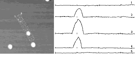
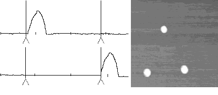
Figure 3 illustrates a manipulation task accomplished with the PC version. It took several hours to position the Au balls to form the “USC” pattern. Clearly, automation is needed if we are to perform more complex tasks routinely.
The basic algorithm for automating positioning operations is the following.
- Scan the sample to obtain an initial image. Set (x, y) = (X, Y), i.e. assume that the robot and task coordinate systems coincide intially.
- Extract from the image the coordinates of the centers of the particles to be moved.
- For each of these particles issue a command to move it in straight line from its current position (X, Y) to the desired position (X + Dx, Y + Dy) in task coordinates.
- To implement a move command for a particle, search for the new (x, y) coordinates of its center, by means of SingleLineScans as explained earlier, and then issue a Push command in robot coordinates.

V. DISCUSSION
We have shown how to move Au balls on a mica substrate with an SPM in NC-AFM mode by issuing manipulation commands to an SPM server in a networked computer environment. Our approach uses a commercially-available SPM and a manufacturer-supplied API that hides the complexities of real-time control from a higher-level robot programmer. We built intermediate-level commands for sensing and acting on top of this API. We succeed in moving a desired particle an estimated 80-90% of the time. However, there is much we don’t understand yet. Here are some of the issues we are currently grappling with.
- Some particles do not move at all, whereas others move only in a few specific directions, and require suitably-chosen intermediate points to reach a desired final position. We do not know why. Particles that are imaged clearly tend to be easy to move.
- Particle motions sometimes fall short of the commanded distances. With additional sensing and pushing the desired positions can still be reached.
- Can we characterize in a predictive fashion which particles are movable on which substrates, or do we have to analyze the situations case by case, possibly by empirical methods?
- Do the strategies described here extend to smaller dimensions, say, to 2 nm particles?
- Do they extend to other particle/substrate pairs? If not, we will not be able to write “generic” pushing software.
- Can useful devices be built by pushing operations?
ACKNOWLEDGEMENT
The research reported in this paper was supported by the Zohrab A. Kaprielian Technology Innovation Fund of the University of Southern California.
REFERENCES
[1] J. A. Stroscio and D. M. Eigler, Science 254, 1319 (1991).
[2] T. Junno et al., Appl. Phys. Lett. 66, 3627 (1995).
[3] T. A. Jung et al., Science 271, 181 (1996).
[4] J. Hu et al., J. Vac. Sc. Technol. B 14, 1341 (1996).
[5] J. Vesenka, S. Manne, R. Giberson, T. Marsh and E. Henderson, Biophysical Journal 65, 992 (1993).
[6] E. A. Hauser, Silicic Science, D. Van Nostrand & Company (1955).
[7] K. Park, H. Park, R. M. Albrecht, Colloidal Gold: Principle Methods and Applications, vol.1, Academic Press (1989).
[8] R. Hunter, Foundation of Colloid Science, Oxford Science Publications, Clarendon Press (1989).
[9] J. Klein and P. F. Luckham, Colloids and surfaces 10, 65 (1984).
[10] Fresh monodisperse colloidal particles prepared from standard reduction processes were from Ted Pella, Redding, CA. The Poly-L-Lysine solution (0.1 %) was from Sigma Diagnostic. The mica sheets were from Electron Microscopy Sciences, Ft. Washington, PA. The overall procedure consisted of adsorbing 20 microlitre of 0.1% Poly-L-Lysine onto freshly cleaved mica for 20-60 s, rinsing with deionized water and drying with nitrogen. Immediately after drying, 20 microlitre of gold colloidal solution was adsorbed onto the treated mica for 5 minutes or more, depending on the surface concentration needed. The sample was then rinsed again with deionized water. After drying with nitrogen it was finally incubated in a 60° C oven for at least one hour.
